

Tolerance Chart For Engineering Drawing
 In the last chapter (Design Inputs & Reviews), we covered the three phases of product design which often result in the creation of detailed engineering drawings associated with your new product.
These Engineering or Technical Drawings serve a number of different purposes.
One of the most important is to capture the intention of the designer and all of the requirements associated with the newly designed product. The next benefit or purpose of the engineering drawing is to act as a communication tool.
As a Quality Engineer you're likely aware that there are many different people within the manufacturing process who will need information about the new components or assemblies that have been designed.
This includes process designers, component buyers, component suppliers, raw material inspectors, assemblers, post-assembly QC inspectors & lastly the customers themselves.
Geometric Dimensioning & Tolerancing
To ensure that your engineering drawings are communicated effectively (error-free), drawing creators (designers) use a technical "communication language" called GD&T or Geometric Dimensioning & Tolerancing.
Before the development of GD&T, traditional engineering drawings often contained many handwritten notes to capture the designers intent.
These handwritten notes became a source of error as organizations began scaling up or when those notes needed to be translated to other languages.
The GD&T methodology was created to standardize the "language" of engineering drawings, so that no matter who you are, or where you were in the world, you could read a drawing and understand exactly what is required for that component.
Today, the GD&T methodology provides a robust method to communicate all of necessary information associated with a component which include; dimensions, tolerances, geometry, materials, finish and all other pieces of information about a drawing (revision, part number, etc).
To do all of this, GD&T utilizes a set of standard symbols to describe the different features or requirements of a component.
These symbols have been able to replace the traditional handwritten notes and ensure a standard approach to dimensioning and tolerancing that is friendly to the manufacturing & inspection world.
GD&T and the Quality Engineer
As a Quality Engineer you will be expected to be able to read and interpret Engineering drawings and the GD&T associated with that drawing.
This will allow you to understand the intent of the product designer, which will allow you to assess the conformance of a unit coming off of your production line.
Additionally, it is not uncommon for designers to identify features that are CTQ (Critical to Quality) on an engineering drawing.
You must be able to interpret these CTQ's and create a Quality Control Plan to measure, monitor & control your process for these critical dimensions.
Interpreting Technical Drawings
There are 7 aspects of the GD&T methodology that we will discuss, these include: Views, Dimensions, Tolerances, Symbols, Datum's, Feature Control Frames & Title Blocks.
Drawing Views
The first tool in your engineering drawing toolbox is the drawing view. Drawing Views are simply the representation of your component from multiple perspectives (Front, Side, Top, etc).
Even the most rudimentary of components cannot be completely understood just by looking at it in one 2-D viewing plane (front). This is why engineering drawings contain multiple views, so that the full geometry of the complete part can be understood.
There are many different views available to the designer (front, back, top, bottom, left, right, isometric), however most engineering drawings contain 3 different views of the same component.
A general rule of thumb is that you should use as few views as possible to fully convey the geometry of the part, and give the reader some perspective of the different features of the component.
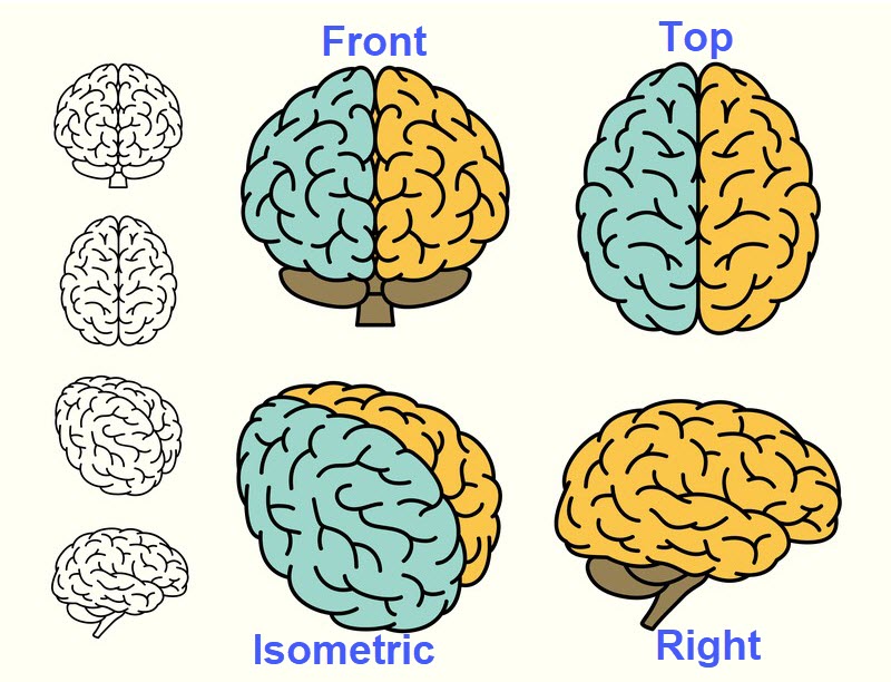
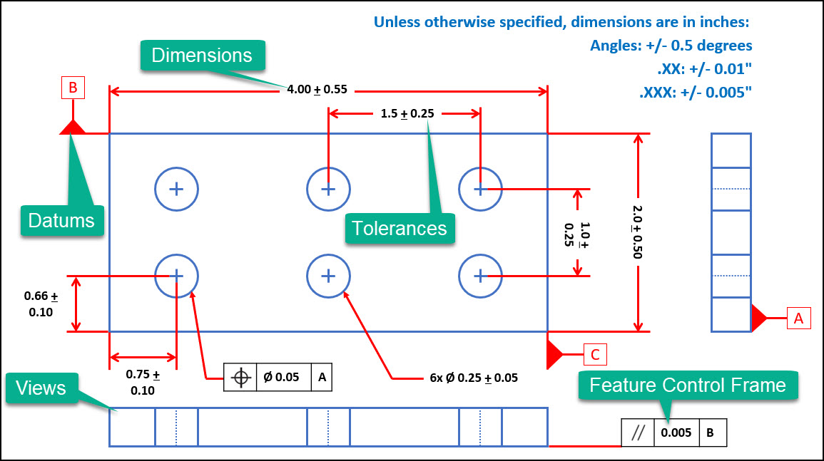
You can see in the drawing above that 4 different view are used, the Front View (top left), Top View (top right), Side View (bottom right) and the Isometric View (bottom left), and these different views set the foundation for how the component will be dimensioned and toleranced.
Do you think we could have safely excluded one of these views without impacting the readers ability to fully grasp the part geometry?
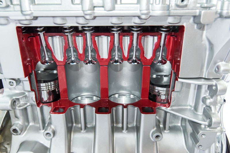
View can also be taken at a cross-section of a component to show internal features or dimensions.
GD&T Dimensions
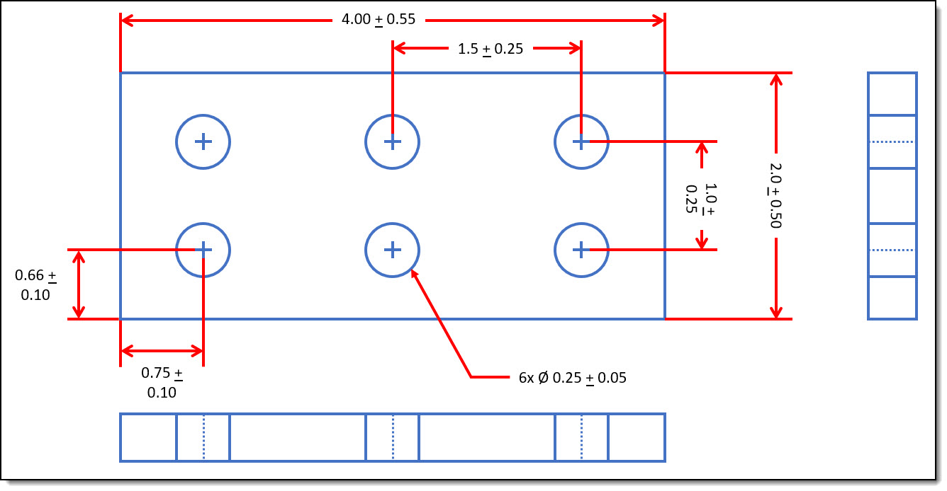
Once you've created the different views on your engineering drawings, it's now time for you to add dimensions to the drawing.
According to ASME Y14.5, dimensions are a numerical value(s) or mathematical expression in appropriate units of measure used to define the form, size, orientation or location, of a part or feature.
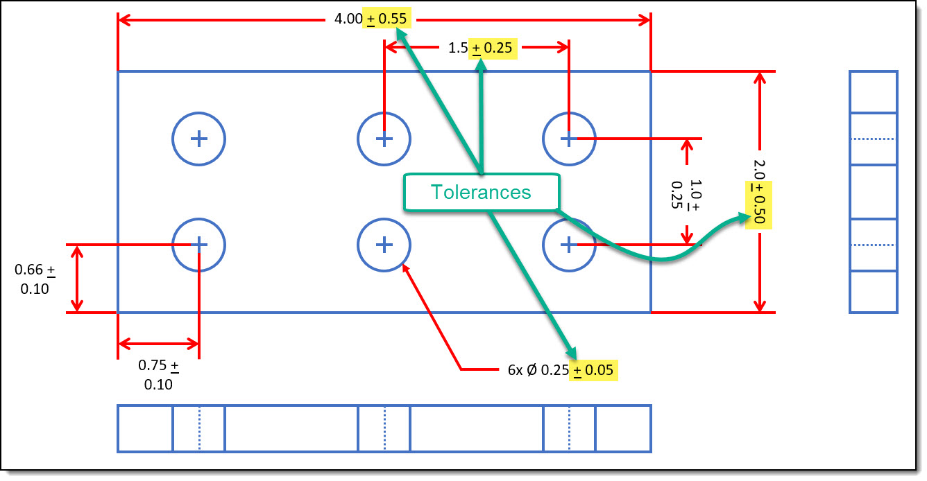
As you can see on the drawing below, dimensions are shown through the usage of "extension lines" (shown in red) that are spaced between the two features being dimensioned. For example, the distance between the centers of two holes (91.2).
To properly dimension your newly designed product, there are a handful of important rules within ASME Y14.5-2009 that you should know:
- Dimensions [and tolerances] shall be complete so there is a full understanding of the characteristics of each feature
- Dimensions should not be subject to more than one interpretation
- Each necessary dimension shall be shown
- Dimensions shall be selected and arranged to suit the function and mating relationship of a part
- Non-mandatory (Reference Only) dimensions shall be identified by an appropriate note
- Dimensions should be arranged for optimum readability
- An angular dimension of 90° is implied for any 2D view where no angle is specified & lines are shown at right angles
- Dimensions [and tolerance] apply only at the drawing level where they are specified
- Dimensions are assumed to apply to the full length, width and depth of a feature unless stated otherwise
Tolerances for those Dimensions
Once you've fully dimensioned all of the features on your drawings, it's now time to talk about tolerances.
According the ASME Y14.5, A tolerance is defined as the total amount that a specific dimension is permitted to vary. This total amount is considered the difference between the maximum and minimum limits.
So why do we even have tolerances???
As you likely already know, nothing is perfect. There is no manufacturing process on the planet that always produces parts at the nominal dimensions.
Your manufacturing process will experience a certain level of variation which can never be fully eliminated, and which can originate from many different sources. This is where the idea of tolerances come into play.
As product designers, and drawing creators, we must account for this expected & natural variation in the form of tolerances which allow our design to vary from the nominal or perfect geometry.
There are 4 different types of tolerances that we need to discuss, these are bilateral tolerances, unilateral tolerances, limit tolerances & single limit tolerances. These four tolerance types are shown below:
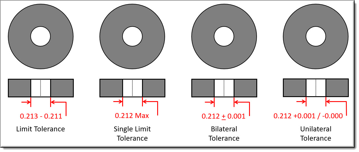
As shown, Limit Tolerances show both a maximum and minimum dimension allowable for the feature. A Single Limit Tolerance only defines one limit dimension, normally either the maximum or minimum value for a feature or dimension.
The Bilateral Tolerance shows the nominal dimension (0.212) and the allowable tolerance in either direction + .001. The Unilateral Tolerance shows the nominal dimension (0.212) and a tolerance in only one direction +0.001.
Tolerancing Via a Note on the Drawings
Another method for tolerancing your dimensions is the usage of standard tolerances. For example, many drawings are created with a note that reads like this:
Unless otherwise specified, dimensions are in inches:
- Angles: +/- 0.5 degrees
- .XX: +/- 0.01″
- .XXX: +/- 0.005″
This allows the designer to put the nominal dimension on the drawing and then let the drawing control the tolerance.
For example, the designer can show a dimension of 1.45″ and the implied tolerance is 0.01″ because the nominal dimension was specified to two decimal places X.XX.
Had the dimension been specified to the third decimal place (1.450″), then the implied dimension would be 0.005″.
Tolerancing Rules
Similar to dimensions, there are a handful of important rules associated with Tolerance found within ASME Y14.5-2009 that you should know:
- All dimensions must have a tolerance – unless they are specified as minimum, maximum or reference only.
- Tolerances [and Dimensions] shall completely define the nominal geometry allowable variation
- Tolerances [and Dimensions] apply only at the drawing level where they are specified
- Tolerances [and Dimensions] should be arranged for optimum readability
- Tolerances [and Dimensions] are assumed to apply to the full length, width and depth of a feature unless stated otherwise
Selecting Proper Tolerances
Tolerances [and dimension] should be selected such that all parts will fit together and function appropriately when assembled.
Tighter tolerances require precision manufacturing equipment which can increase the overhead cost associated with production.
Tighter tolerances can also require higher precision measurement equipment, more frequent inspections, in depth operator & inspector training and inspection processes that are time consuming.
All of these factors add up to the increased cost associated with tighter tolerances.
This is where a Robust Design can be so valuable, if the same level of quality can be achieved with looser tolerances, it can save your organization a lot of money in the long run.
GD&T Symbols for Tolerancing
The last comment I'll make on tolerances is that they don't just apply to dimensions, they can also apply to many other features or characteristics about your part including straightness, flatness, position, orientation, etc.
This is where the usage of GD&T Symbols becomes extremely important.
One of the benefits of GD&T is the usage of common symbols that are used to further tolerance a part all of the different characteristics of a component that can be critical.
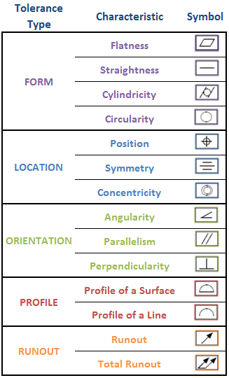
Below is a table showing the 14 standard geometric tolerance symbols used in geometric tolerancing as defined by ASME Y14.5. These geometric tolerances fall into one of five categories – Form, Location, Orientation, Profile & Runout.
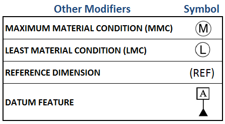
Additional Modifying Symbols
In addition to these geometric tolerance symbols, there a handful of other modifier symbols that you should be familiar with, these are shown below:
Datum & Datum Feature
Now that we've got the symbols down, it's time to introduce the next important topic to an engineering drawing; the Datum & the Datum Feature.
A Datum is an imaginary plane, axis, point, line or cylinder that are the origins from which the location of geometric characteristics of features are established.
Datum's are theoretical and only simulated by Measurement Equipment (Gauge pins, Granite slabs, angle plates, etc).
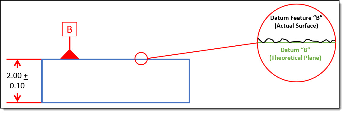
A Datum Feature on the other hand is a physical feature of a part that are used to establish the imaginary datum's.
Datum Features are real, tangible features on a part where the measurement equipment would physically touch or measure.
Datum's and Datum features are both important because they become the frame of reference against which measurements are taken. You can see the difference between the actual (datum feature) and theoretical (datum) below.
Now that we've got that down we're ready to discuss the last and possibly the most important topic within the GD&T methodology, the Feature Control Frame.
Feature Control Frame
The Feature Control Frame is potentially the most useful tool in any geometric tolerancing system because it allows you to effectively use all of the geometric tolerancing symbols available to you.
A Feature Control Frame is a GD&T Tool that combines a Geometric Characteristic, the tolerance allowed (Tolerance Zone shape & Tolerance Zone Size), any material modifiers, and the datum feature references to create a geometric tolerance .
Feature Control Frames are an effective & compact method for providing clear & concise requirements for the many different features of your design. The Feature Control Frame can be broken down into three sections, shown here in blue.

The first box or section can contain any of the 14 different standard geometric tolerance symbols found above. In this example, the feature control frame includes a True Position Tolerance.
The next section contains the actual tolerance for the specific feature being toleranced. In this example, the true position tolerance is 0.25 with an additional diameter symbol to indicate a circular tolerance zone at maximum material condition (M)
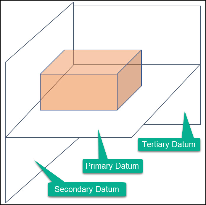
The third and final section indicate the datum references associated with the tolerance. In this example Datum A is the primary datum, Datum B is the secondary datum, and Datum C is the tertiary datum. This datum order is important because it standardizes the way the part is fixtured during inspection.
Title Block
The very last item that we need to cover is the Title Block. The title block of any drawing can usually be found in the bottom right hand corner of most drawings and contains a ton of important information.
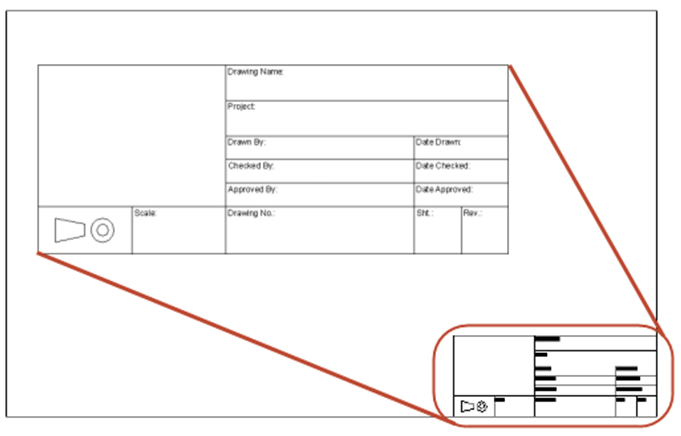 In fact the first time you pick up any sort of engineering drawing, the first place you should always look is the title block. This is where you'll often find:
- the Component Part Number
- the Drawing Description
- the Bill of Material or Parts List
- the Revision Level of the Drawing
- the Standard Tolerances
- the Units of Measure & Scale
- the Required Material &/or Finish
- the number of sheets associated with the drawing
Conclusion
Alright, so we've unfortunately just skimmed the surface of the GD&T universe, but I believe we've covered everything that would be in scope of the CQE certification exam.
This includes a quick discussion of the following 7 GD&T Tools: Views, Dimensions, Tolerances, Symbols, Datum's, Feature Control Frames & Title Blocks.
Below is an example of an engineering drawing containing all of these elements besides the title block.
I think it's important to reiterate that Engineering Drawings are a critical tool in the world of Quality.
First because they capture the design intent associated with your product and clearly communicates all of the important requirements associated with your product to the multitude of individuals who are involved in bringing your product to life.
Alright – ready for a practice quiz?
Practice Quiz
Technical Drawings & Specifications
0 of 14 questions completed
Questions:
- 1
- 2
- 3
- 4
- 5
- 6
- 7
- 8
- 9
- 10
- 11
- 12
- 13
- 14
Information
This quiz covers the Technical Drawings & Specifications chapter of the Product & Process Design pillar.
You have already completed the quiz before. Hence you can not start it again.
Quiz is loading...
You must sign in or sign up to start the quiz.
You have to finish following quiz, to start this quiz:
0 of 14 questions answered correctly
Your time:
Time has elapsed
You have reached 0 of 0 points, (0)
| Average score | |
| Your score |
Categories
- Technical Drawings & Specs 0%
-
So how did you do?
Were you able to remember as much as you thought you could?
Were you able to complete the exam in a timely manner?Wanna give me some feedback about the quiz – shoot me an email or contact me!
Ready to keep studying – find another chapter!
- 1
- 2
- 3
- 4
- 5
- 6
- 7
- 8
- 9
- 10
- 11
- 12
- 13
- 14
- Answered
- Review
-
Question 1 of 14
Category: Technical Drawings & Specs
What is the tolerance associated with the following dimension:
5.00 + 0.10″
Correct
Remember – A tolerance is defined as the total amount that a specific dimension is permitted to vary.
This total amount is considered the difference between the maximum and minimum limits.5.10 – 4.90 = 0.20″ or 2 x 0.10″ = 0.20″
Incorrect
Remember – A tolerance is defined as the total amount that a specific dimension is permitted to vary.
This total amount is considered the difference between the maximum and minimum limits.5.10 – 4.90 = 0.20″ or 2 x 0.10″ = 0.20″
-
Question 2 of 14
Category: Technical Drawings & Specs
Match the following geometric tolerance type with its appropriate tolerance category:
- Tolerance of Form
- Tolerance of Orientation
- Tolerance of Location
- Profile Tolerance
- Runout Tolerance
Correct
- Flatness = Form Tolerance
- Perpendicularity = Orientation Tolerance
- Symmetry = Location Tolerance
- Profile of a Surface = Profile Tolerance
- Total Runout = Runout Tolerance
Incorrect
- Flatness = Form Tolerance
- Perpendicularity = Orientation Tolerance
- Symmetry = Location Tolerance
- Profile of a Surface = Profile Tolerance
- Total Runout = Runout Tolerance
-
Question 3 of 14
Category: Technical Drawings & Specs
Based on the dimensioning & tolerancing of the drawing below:

Identify all of the true statements below regarding Dimension A:
Correct
A = 65 + 0.15″ – 40 + 0.15″ = 25 + 0.30″
Max A = 65.15 – 39.85 = 25.30″ or 25 + .30″
Min A = 64.85 – 40.15 = 24.70″ or 25 – .30″
Tolerance A = Max A – Min A = 25.30 – 24.70 = .60 or + .30″
Incorrect
A = 65 + 0.15″ – 40 + 0.15″ = 25 + 0.30″
Max A = 65.15 – 39.85 = 25.30″ or 25 + .30″
Min A = 64.85 – 40.15 = 24.70″ or 25 – .30″
Tolerance A = Max A – Min A = 25.30 – 24.70 = .60 or + .30″
-
Question 4 of 14
Category: Technical Drawings & Specs
Match the following dimension & tolerances with it's tolerance type:
- Unilateral Tolerance
- Bilateral Tolerance
- Single Limit Tolerance
- Limit Tolerance
Correct

.
Incorrect
.
-
Question 5 of 14
Category: Technical Drawings & Specs
Match the following tolerance with the correct symbol:
- Cylindricity
- Concentricity
- Flatness
- Position
- Runout
-
Question 6 of 14
Category: Technical Drawings & Specs
Identify all of the statements below regarding dimensions & tolerances which are true :
Correct
The following statements are true :
- Dimensions and tolerances shall be complete so there is a full understanding of the characteristics of each feature
- Each necessary dimension shall be shown
- Dimensions should not be subject to more than one interpretation
- An angular dimension of 90° is implied for any 2D view where no angle is specified & lines are shown at right angles
The following dimensions are false :
- Parts dimensions shall be selected and arranged to suit the
manufacturing operationfunction and mating relationship of a part - Dimensions and tolerance apply
at all drawing levels where the component is utilizedonly at the drawing level where they are specified
Incorrect
The following statements are true :
- Dimensions and tolerances shall be complete so there is a full understanding of the characteristics of each feature
- Each necessary dimension shall be shown
- Dimensions should not be subject to more than one interpretation
- An angular dimension of 90° is implied for any 2D view where no angle is specified & lines are shown at right angles
The following dimensions are false :
- Parts dimensions shall be selected and arranged to suit the
manufacturing operationfunction and mating relationship of a part - Dimensions and tolerance apply
at all drawing levels where the component is utilizedonly at the drawing level where they are specified
-
Question 7 of 14
Category: Technical Drawings & Specs
 Identify all of the statements below which are true regarding the following drawing:
Correct
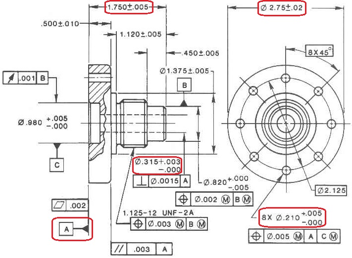 The following statements are True :
- The Nominal Dimension of the Center Through Hole is 0.315″
- The Maximum Material Condition (MMC) for the overall height of the structure is 1.755″
- Datum A is called out as the bottom surface of the base
The following statements are false :
- the
Least Material Condition (LMC)Maximum Material Condition (MMC) for the 8 unique through holes on the base of the structure is 0.210″.- For a through hole, the least material condition is actually the largest hole size dimension, which is 0.215″. In this case, the nominal dimension of 0.210″ represents the smallest potential hole size because of the -0.000 tolerance, thus making it the maximum material condition.
- If this is confusing, you may think of it like this – the smallest hole diameter means that more material is on the part, or less material is removed to create the hole; and as the hole gets bigger in diameter, more material would have to be removed.
- The Least Material Condition (LMC) for the overall base diameter is
2.75″2.73″. 2.75 is the nominal dimension and the Least Material Condition occurs as the lower tolerance limit of the dimension, 2.73″.
Incorrect
The following statements are True :- The Nominal Dimension of the Center Through Hole is 0.315″
- The Maximum Material Condition (MMC) for the overall height of the structure is 1.755″
- Datum A is called out as the bottom surface of the base
The following statements are false :
- the
Least Material Condition (LMC)Maximum Material Condition (MMC) for the 8 unique through holes on the base of the structure is 0.210″.- For a through hole, the least material condition is actually the largest hole size dimension, which is 0.215″. In this case, the nominal dimension of 0.210″ represents the smallest potential hole size because of the -0.000 tolerance, thus making it the maximum material condition.
- If this is confusing, you may think of it like this – the smallest hole diameter means that more material is on the part, or less material is removed to create the hole; and as the hole gets bigger in diameter, more material would have to be removed.
- The Least Material Condition (LMC) for the overall base diameter is
2.75″2.73″. 2.75 is the nominal dimension and the Least Material Condition occurs as the lower tolerance limit of the dimension, 2.73″.
-
Question 8 of 14
Category: Technical Drawings & Specs
Identify all of the geometric tolerance symbols in the following drawing:

Correct
 This drawing contains the following symbols:
- Perpendicularity
- Position or True Position
- Parallelism
- Flatness
This drawing does not contain :
- Circularity
- Straightness
- Angularity
Incorrect
This drawing contains the following symbols:- Perpendicularity
- Position or True Position
- Parallelism
- Flatness
This drawing does not contain :
- Circularity
- Straightness
- Angularity
-
Question 9 of 14
Category: Technical Drawings & Specs
Identify all of the statements below regarding the following drawing, which are false :

Correct
 The following statements are False:
 - Datum C can be described as the
Top SurfaceLeft Surface - The Secondary Datum for the Positional Tolerance of the 4 holes is Datum
AB - Datum B can be described as the
Left SurfaceBottom Surface
The following statements are True :
- The overall length is 123.2
- Datum A can be described as the Front Surface
Incorrect
The following statements are False: - Datum C can be described as the
Top SurfaceLeft Surface - The Secondary Datum for the Positional Tolerance of the 4 holes is Datum
AB - Datum B can be described as the
Left SurfaceBottom Surface
The following statements are True :
- The overall length is 123.2
- Datum A can be described as the Front Surface
-
Question 10 of 14
Category: Technical Drawings & Specs
Identify all of the statements below regarding the following drawing which are true :

Correct
 The following statements are true :
- The Perpendicularity of Datum B = .1mm as measured from Datum A – See feature control frame highlighted in the lower left hand corner.
- The MMC (Maximum Material Condition) of the part Height = 100.2mm – The tolerance of the basic dimension of 100mm (height) is allows to vary by + 0.2mm which means that the maximum material condition is 100.2mm.
- The distance between through holes is 70mm – (85 – 15 = 70mm)
The following statements are false :
- The
MMCLMC of the Through Hole is 20.1mm – Remember the MMC for a hole is when the least amount of material is removed, thus leaving the most amount of material on the part itself. Therefore, the MMC for the through hole is its smallest dimension (19.9mm), while 20.1mm represents the Least Material Condition (LMC). - The
ParallelismFlatness between the top & bottom surface = .1mm - The Position of the through holes can vary by 0.3mm at
LMCMMC – the feature control frame for the position of the through holes indicates that the tolerance can vary by 0.3mm at Maximum Material Condition.
Incorrect
The following statements are true :- The Perpendicularity of Datum B = .1mm as measured from Datum A – See feature control frame highlighted in the lower left hand corner.
- The MMC (Maximum Material Condition) of the part Height = 100.2mm – The tolerance of the basic dimension of 100mm (height) is allows to vary by + 0.2mm which means that the maximum material condition is 100.2mm.
- The distance between through holes is 70mm – (85 – 15 = 70mm)
The following statements are false :
- The
MMCLMC of the Through Hole is 20.1mm – Remember the MMC for a hole is when the least amount of material is removed, thus leaving the most amount of material on the part itself. Therefore, the MMC for the through hole is its smallest dimension (19.9mm), while 20.1mm represents the Least Material Condition (LMC). - The
ParallelismFlatness between the top & bottom surface = .1mm - The Position of the through holes can vary by 0.3mm at
LMCMMC – the feature control frame for the position of the through holes indicates that the tolerance can vary by 0.3mm at Maximum Material Condition.
-
Question 11 of 14
Category: Technical Drawings & Specs
Identify all of the geometric tolerance symbols below that are considers tolerances of form .
Correct
 The following geometric symbols are considered tolerances of form:
- Flatness
- Straightness
The other two tolerances of form which were not shown are:
- Cylindricity
- Circularity
The following symbols are not considered tolerances of form:
- Symmetry is a tolerance of Location
- Angularity is a tolerance of Orientation
- Position is a tolerance of Location
Incorrect
The following geometric symbols are considered tolerances of form:- Flatness
- Straightness
The other two tolerances of form which were not shown are:
- Cylindricity
- Circularity
The following symbols are not considered tolerances of form:
- Symmetry is a tolerance of Location
- Angularity is a tolerance of Orientation
- Position is a tolerance of Location
-
Question 12 of 14
Category: Technical Drawings & Specs
A ______________ is defined as a numerical value(s) or mathematical expression in appropriate units of measure used to define the form, size, orientation or location, of a part or feature.
Correct
A dimension is defined as a numerical value(s) or mathematical expression in appropriate units of measure used to define the form, size, orientation or location, of a part or feature.
Incorrect
A dimension is defined as a numerical value(s) or mathematical expression in appropriate units of measure used to define the form, size, orientation or location, of a part or feature.
-
Question 13 of 14
Category: Technical Drawings & Specs
 Match the following 4 features on this drawing in blue to their proper description below:
- Dimensions & Tolerances
- Datums
- Feature Control Frames
- Geometric Tolerancing Symbols
Correct
Feature A = Dimensions & Tolerances
Feature B = Datums
Feature C = Feature Control Frames
Feature D = Geometric Tolerancing Symbols
Incorrect
Feature A = Dimensions & Tolerances
Feature B = Datums
Feature C = Feature Control Frames
Feature D = Geometric Tolerancing Symbols
-
Question 14 of 14
Category: Technical Drawings & Specs
A _______________ is defined as the total amount that a specific dimension is permitted to vary. This total amount is considered the difference between the maximum and minimum limits.
Correct
A tolerance is defined as the total amount that a specific dimension is permitted to vary. This total amount is considered the difference between the maximum and minimum limits.
Incorrect
A tolerance is defined as the total amount that a specific dimension is permitted to vary. This total amount is considered the difference between the maximum and minimum limits.


Next: Product and Process Control
Tolerance Chart For Engineering Drawing
Source: https://cqeacademy.com/cqe-body-of-knowledge/product-process-design/technical-drawings-gdt/
Posted by: salasgrandise.blogspot.com
0 Response to "Tolerance Chart For Engineering Drawing"
Post a Comment